The Scrapyard

scrapyard /skɹæpjɑː(ɹ)d/ n. (pl. -s) 1 A junkyard, a place where scrap is stored, discarded or resold. 2 A place for tinkerers and kludgers to store important parts for later.

This is where I collect my parts: information I’ve gathered, projects I’ve worked on, and whatever else I find that might be useful or interesting. You can also check out my GitHub repositories here.


Hardware

  1. RF Power Reference
    A small, 120 MHz, +2dBm ±1dB power reference board.

  2. LED SMPS Driver
    PWM-controllable current supply for high-power LEDs up to 14 W.

  3. Hypnojelly
    A glowing plastic jellyfish, as a toy for infants.

FPGAs

  1. Microwave Frequency Counter
    A reciprocal frequency counter implemented on a Xilinx Spartan-6 FPGA, currently with a range of about 400 Hz to 400 MHz and a precision of four digits.

  2. OLED Module Interface
    Low-level interface for a Digilent OLED peripheral module.

  3. Clock Synchronization
    Creating a PLL using only digital logic, to synchronize a high-frequency clock derived from the master FPGA clock to an external low frequency reference signal.

  4. AVR Programmer
    An implementation of the STK500 protocol.

  5. Digital Filters
    Efficient implementation of a narrowband matched filter

Software

  1. Linux DVD-A Decryption
    A library to decrypt DVD-Audio discs.

  2. Evolutionary optimization of a keycap group buy
    Using genetic algorithms to determine, given a maximum number of key labels, the optimal set of labels that covers as many known Ergodox keyboard layouts as possible.

  3. GPX Path Smoothing
    Given a GPS track in GPX format, remove points to smooth the path without significantly degrading the accuracy.

Gardening

  1. Succulents
    Various interesting succulents I’ve found or grown.


Miscellaneous Ramblings

Compiling RP2040 QMK Firmware on Slackware

Compiling QMK keyboard firmware for an RP2040 microcontroller on Slackware is not a one-click operation.

The first difficulty is that the RP2040 is a Cortex-M0+ CPU with no floating-point unit, but the Slackbuilds version of arm-gcc is built to default to Cortex-M3 with a hard FPU. The result is the not supported error given below. Fixing this requires compiling a custom version of arm-gcc, as all of the supporting libraries (newlib, for instance) also need to be compiled with the new settings.

sorry, unimplemented: Thumb-1 hard-float VFP ABI

In the arm-gcc slackbuild, change --with-float=hard to--with-float=soft, and remove the --with-fpu= line. Build arm-gcc, and rebuild newlib as well if that was installed with the standard arm-gcc.

The second issue has to do with newlib: since 2021 QMK uses newlib-nano, which is not available in Slackbuilds. To fix, edit platforms/chibios/platform.mk and remove the argument --specs=nano.specs from the definition of TOOLCHAIN_LDFLAGS.

/usr/bin/arm-none-eabi-ld: cannot find -lg_nano
/usr/bin/arm-none-eabi-ld: cannot find -lc_nano

T-Slot Rail 10" Network Rack

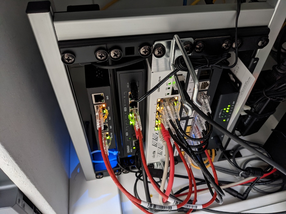
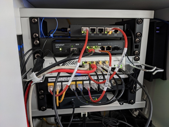
My “networking closet” was a mess but is too narrow for a 19” rack, so I built a 10” rack out of McMaster t-slot rails (5537T35) and hardware. It’s mounted to the wall using an L-shaped foot (5537T571) at the lower left and a rearwards-extending segment of rail at the upper left, so quite sturdy. The 5U rack strips are attached unmodified using slot hardware, on matching-length t-slot rails mounted such that the spacing between them can be adjusted: not all “half-rack” hardware is exactly 10”, I’ve found.

No space on the rack to mount power supplies, servers, or much in the way of cable organizers, but at least the network hardware is now accessible and somewhat organized.

Rack hardware, for reference:

  • Mikrotik RB450Gx4 (router, DHCP, DNS, etc…)
  • QNAP QSW-2104-2S (2.5GBASE-T switch, for NAS and office workstation)
  • Mikrotik CSS610-8G-2S+IN (1GBASE-T switch, wanted a POE model but it didn’t have SFP+)
  • Uxcell 12-port keystone panel
  • UTT S1042GP (POE switch, for APs)

Below the rack:

  • Azulle Byte3 (NUC as lightweight FreeBSD server)
  • Supermicro SYS-5029A-2TN4 (TrueNAS)

The in-wall cabling for APs (Ruckus R500 and Mikrotik wAP ac) and for my home office terminates on the 12-port patch panel. The panel also connects to the printer and to a HomeSeer RPI HomeTroller V3.

Front View

Front View

Controlling pulseaudio spawned by a systemd service

TL/DR: you can run pavucontrol under systemd-run to interact with a pulseadio server spawned by a system service.

I run Music Player Daemon on my NAS and stream the output via Roc Toolkit to multiple clients scattered around the house. My first client was a NUC running Slackware, but I wanted somthing more efficient so picked up a few Raspberry Pi’s, and for simplicity stuck with the official linux distribution, running systemd. It was easy enough to create a unit file to run roc-recv as a system service, but systemd isolates services and user sessions in silos, with as a result that commands such as pactl and pavucontrol couldn’t connect to the roc-spawned pulse server. The solution is to use systemd-run to run pa* as a system process.

$ ssh -Y pi@audio3A

pi@audio3A:~ $ systemctl status roc
● roc.service - Roc-toolkit receiver
   Loaded: loaded (/etc/systemd/system/roc.service; disabled; vendor preset: enabled)
   Active: active (running) since Fri 2022-01-14 09:28:54 PST; 57min ago
 Main PID: 25923 (roc-recv)
    Tasks: 5 (limit: 873)
   CGroup: /system.slice/roc.service
           ├─25923 /usr/bin/roc-recv -d pulse -s rtp+rs8m::10001 -r rs8m::10002 --sess-latency=1s --min-latency=-1s --max-latency=2s --np-timeout=2s --bp-timeout=2s
           └─25928 /usr/bin/pulseaudio --start --log-target=syslog

pi@audio3A:~ $ ps aux | grep roc-recv
pi       25923 29.0  1.8 300744  8096 ?        R<sl 09:28  16:55 /usr/bin/roc-recv -d pulse -s rtp+rs8m::10001 -r rs8m::10002 --sess-latency=1s --min-latency=-1s --max-latency=2s --np-timeout=2s --bp-timeout=2s

pi@audio3A:~ $ id pi
uid=1000(pi) gid=1000(pi) groups=1000(pi),4(adm),20(dialout),24(cdrom),27(sudo),29(audio),44(video),46(plugdev),60(games),100(users),105(input),109(netdev),112(bluetooth),999(spi),998(i2c),997(gpio)

pi@audio3A:~ $ sudo systemd-run --uid=1000 pavucontrol --display=$DISPLAY
Running as unit: run-rf850349930a5473787407a1b661c4ac2.service

pi@audio3A:~ $ systemctl status run-rf850349930a5473787407a1b661c4ac2.service
● run-rf850349930a5473787407a1b661c4ac2.service - /usr/bin/pavucontrol --display=localhost:10.0
   Loaded: loaded (/run/systemd/transient/run-rf850349930a5473787407a1b661c4ac2.service; transient)
Transient: yes
   Active: active (running) since Fri 2022-01-14 10:13:09 PST; 10min ago
 Main PID: 26500 (pavucontrol)
    Tasks: 2 (limit: 873)
   CGroup: /system.slice/run-rf850349930a5473787407a1b661c4ac2.service
           └─26500 /usr/bin/pavucontrol --display=localhost:10.0

Jan 14 10:13:09 audio3A systemd[1]: Started /usr/bin/pavucontrol --display=localhost:10.0.

Repairing a Berenice D12 LED

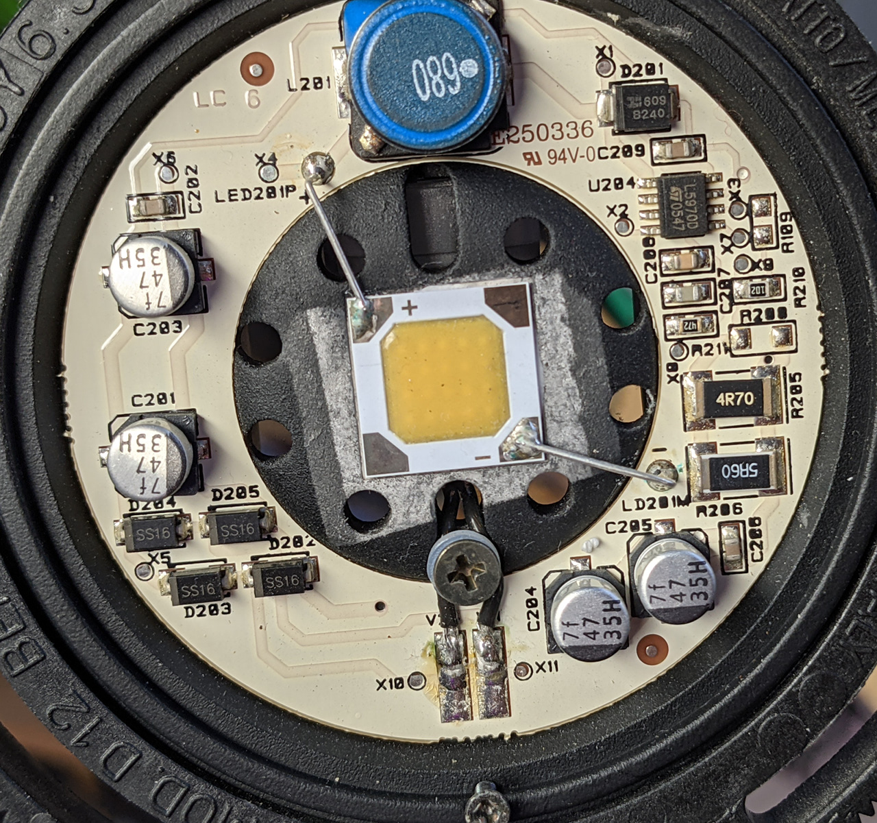
I own a Luceplan Berenice D12 LED table lamp. Very nice lamp that has served me well for many years as both a desk and readling light, but recently it began to flicker. The lamp has a warning that the bulb is not user-replaceable and the company didn’t respond to my email, so I took the lamp head apart to see what was up. The LED driver in the lamp head is a straightforward L5970D step-down converter set up for a constant 460 mA through a square ~1.5 cm LED. The flickering was due to rows of the 5x5 emitter grid shutting off intermittently once warmed up, for whatever reason.

The existing passive components appeared to be in order so I removed the existing unmarked bulb (glued in place, twist to remove) and replaced it with a Cree CXA1507. The D12 heatsink has a slight recess for the LED and the Cree is slightly too large, so it’s to be determined if the thermal connection is good enough to prevent it from overheating. However, the driver voltage and light output is stable and the Cree radiation pattern looks to work well with the lens cover of the D12, so thus far the repair is a success.

lamp LED driver PCB

Haskell FFI and Multithreading

TLDR: If you call into long-duration foreign functions from in Haskell and those functions are marked unsafe, other Haskell threads will be paused a la Python’s GIL.

Haskell foreign function calls imported via foreign import ccall can be marked as either safe or unsafe, with complex performance implications. To quote the Typed Pointers section of Real Word Haskell:

When making a foreign import declaration, we can optionally specify a “safety” level to use when making the call, using either the safe or unsafe keyword. A safe call is less efficient, but guarantees that the Haskell system can be safely called into from C. An “unsafe” call has far less overhead, but the C code that is called must not call back into Haskell. By default foreign imports are “safe”, but in practice it is rare for C code to call back into Haskell, so for efficiency we mostly use “unsafe” calls.

However, to quote GHC Threading and FFI:

Here is how GHC does it. So an OS thread with a capability is happily churning along Haskell threads. Suddenly one unbound Haskell thread safe-calls C. (The story of the bound case is in the next section.) This Haskell thread is suspended, this OS thread loses its capability and runs the C code, and some other OS thread gains the capability and picks up the other Haskell threads. Everyone is happy.

An unsafe C call does not involve a transfer of capability. Therefore many other Haskell threads are put on hold as collateral damage.

This behaviour caused me a fair bit of grief, mainly because I was entirely unaware of the nature of what was going on. I’ve been working on some SDR software in Haskell, and the rtlsdr package imports all its calls as unsafe, such that data processing cannot be done concurrently with a call to readSync() due to the capabilities effects discussed above. Modifying the library to use safe imports makes it possible to run the readSync() in a separate OS thread and pass the data via MVar, allowing real-time processing.

FreeBSD 12 and EFI

I ran into all sorts of EFI troubles when installing FreeBSD 12.1 to an ASRock Q1900. The system would not boot properly regardless of how the disk was partitioned and formatted (UFS/ZFS, GPT/MBR, whatever), failing to find the EFI boot partition on the new install, and then stopping with various different errors just after /boot/entropy if booted via legacy bios.

The solution: after installing, reboot using the install media, drop into a shell, and use efibootmgr to add an EFI entry for the newly-installed disk.

On a side note, updating the BIOS to 2.0 doesn’t help either, but also means the system will no longer boot without a monitor attached… 😑

# mount -t msdosfs /dev/ada0p1 /mnt
# efibootmgr -c -l /mnt/efi/boot/BOOTx64.efi -L FreeBSD
BootCurrent: 0003
Timeout    : 1 seconds
BootOrder  : 0000, 0003
 Boot0000  FreeBSD
+Boot0003* UEFI:  USB DISK PMAP
# efibootmgr -a 0
BootCurrent: 0003
Timeout    : 1 seconds
BootOrder  : 0000, 0003
 Boot0000* FreeBSD
+Boot0003* UEFI:  USB DISK PMAP
# efibootmgr -n 0
BootNext : 0000
BootCurrent: 0003
Timeout    : 1 seconds
BootOrder  : 0000, 0003
 Boot0000* FreeBSD
+Boot0003* UEFI:  USB DISK PMAP

FreeBSD and Jellyfin

I’ve made another attempt at getting Jellyfin to run in a jail (see 2020/03/13), since there’s been progress on getting the .NET core to build on FreeBSD (see github). However, although the bootstrap SDK starts in a FreeBSD jail, it still fails with 0x8007001F. Checking with truss, it appears to be failing on an mlock of 4 KiB.

First point: it may be possible to get this running in the base FreeNAS install. The SDK will run .NET executables in the base install if you set an LD_LIBRARY_PATH pointing to the missing libraries (find them in a jail) and if you increase vm.max_wired to allow for the mlock. However, building now fails with a .NET stack trace, one which I haven’t yet tried to debug.

Second point: since mlock works in base, shouldn’t it be possible to have it work in a jail? Iocage has a jail property allow_mlock, but it seems this is a no-op under 11.3, and only actually supported in FreeBSD 12. Thus, memory locking will not work under the current stable version of FreeNAS.

Linux Jail on FreeNAS 13.1

In an attempt to get Jellyfin working in a FreeNAS jail, I installed a Linux runtime in a FreeBSD jail. This is very unsupported, but is possible in conjunction with the linux compatibility layer.

My first attempt followed the instructions from here and here. Installing Devuan worked (a slight scare during apt where it rebooted my machine, but no harm), but the jail had no network access just as in this post. Assuming it was a Debian issue, I tried again with a manual install of Slackware, but encountered the same issues. It’s possible to get an ethernet interface in the jail by enabling vnet, creating an epair interface, and setting the vnet_interface property of the jail (see here), but trying to set an address results in an error:

root@slackware:/# ifconfig epair27b 172.22.0.27
SIOCSIFADDR: Invalid argument
SIOCSIFFLAGS: Invalid argument

Here’s the workaround: since all this is being run with the BSD kernel and via the compatibility layer, it’s possible to mix Linux and FreeBSD executables, so copy over the following files:

/sbin/ifconfig
/sbin/route
/lib/libc.so.7
/lib/libjail.so.1
/lib/libm.so.5
/libexec/ld-elf.so.1

It’s then possible to manually set an address. Not all tools work - ping gets into an infinite loop, for instance - but the package manager works, and that was enough for my purposes.

As far as getting .NET working in the jail, it produces the same error as it does in a FreeBSD jail. Appears to be due to a missing syscall “membarrier”.

Failed to create CoreCLR, HRESULT: 0x8007001F

RouterOS on DigitalOcean

It’s possible to run Mikrotik’s RouterOS on a DigitalOcean standard 1-CPU droplet - see instructions here.

I need a VPN exiting in Europe and for various reasons decided to roll my own. Initially set one up running FreeBSD 12, but was getting a miserly 20 kbps upload speed. It turns out a 1-CPU droplet is not fast enough to run ipfw and natd, or at least not without tuning that’s beyond my level of expertise. I am fairly familiar with RouterOS, however, so installed that on a droplet and did some speed tests: with basic filtering, nat, and using fasttrack to speed up the firewall, I’m getting ~ 3 Mbps in both directions to the US with minimal CPU load on the droplet.

Pros: speed, low cpu usage, powerful networking interface (if you like RouterOS)

Cons: not technically a supported OS, only supports TCP-based OpenVPN connections

Bicycle Mods

Got a bike a few years back that I’m mostly very happy with (Fairdale Weekender), except that I prefer the upright sitting position of a European city bike to the more forward-leaning posture that the Archer handlebar put me in. I finally decided to replace the handlebar with something more to my liking and ended up purchasing the Nitto Bosco on a 105 mm Nitto HiRiser stem, which puts me almost upright. Didn’t much like the trigger shifter on this setup, so I switched it out for a bar-end friction shifter instead.

One caveat: The SunRace R90 rear bar-end shifter is not entirely compatible with the SRAM X5 9-speed rear derailer. The throw of the shifter is not enough to pull the X5 from lowest to highest, so I’ve had to set it to shift from 2nd at minimum to 8th at maximum. We’ll see how well that works for commuting over the next few weeks - whether I miss having the full range, and/or whether I should switch it to 1-7 or 3-9.

Otherwise, I’ll consider switching out the cassette to a 7-speed or switch to a different derailer.

bike

Setting up for IndieWeb, Microformats, etc...

Looks like some people over at IndieWeb.org are trying to get the ball rolling on distributed social networking and such. Looks interesting enough to give a shot, so I’ve reformatted this to be a h-entry post, and added a h-card to the bottom of this page.

Update 5/4: I’ve got an h-card, a rel=me link, and indieauth set up as an auth provider. I’ve got these posts tagged as entries within an h-feed. However, it’s still not entirely clear how this is supposed to work, mostly on the client/consumer side of things. How does one put together a feed out of individual people’s content? Allowing comments on here would be interesting too, although probably not obvious considering the pages are static html.

Currently working on getting auth (via https://indieauth.com), microsub, webmentions (via https://webmention.io) and such up and running, as maybe that’ll make thing clearer.

The webmentions system at https://telegraph.p3k.io doesn’t seem to like twitter as a webmention source, unfortunately. Tweeted a link to this post but Telegraph doesn’t detect the webmention, possibly due to Twitter not having any microformat tags?

Swagelok QC-6 Stem Protectors

I dive sidemount with a manifolded setup, and connect my first stages to the manifold through quick-disconnects. I’ve recently switched to Swagelok QC-6 QDs (another common alternative is Omniswivel), and was looking to attach some stem and body protectors to my setup. Below is how I ended up attaching a loop of cave line to a SS-QC6-SP.

There appear to be two variants of the SS-QC6-SP: one with a hole through the side of the top, with a loop of steel rope through it, and one with a length of steel rope riveted to the top surface. To attach cave line to the latter, drill out the rivet head, push out the body using a hammer and awl, and thread a loop through the resulting hole with knots on both sides to hold it in place. This is easier to do with the cap removed from the body, but be prepared to use force as there was thread lock on the set I received.

SP w/ cap removed SP cap w/ line loop SP w/ line attached
SS-QC6-SP, with steel wire drilled out, in various stages of adding a loop

Lightning

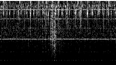
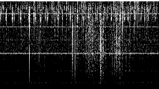
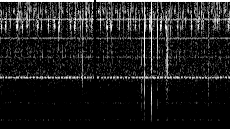
A lightning storm hit today, so I recorded a few strikes. The spectrogram is a 256-point FFT at 100 kSPS, but with every second FFT discarded due to a lack of processing power - otherwise the computer would not have been able to keep up with the radio. The CIC filter in the downsampler has a null at 50 kHz.

Various lightning strikes, each image roughly 1 second wide and from DC to 50 kHz

Aliasing

Just wanted to share an example of why antialiasing matters.

spectrogram
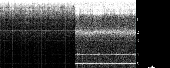
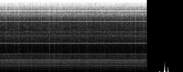
Spectrogram and histogram, roughly 15 seconds, from DC at the top to 50 kHz at the bottom, left with a CIC filter and right without

The above image was captured with the same setup as below: 1 MSPS ADC w/ 500 kHz antialiasing filter, downsampled to 100 kSPS. A switchable bypass was added around the CIC filter, however, allowing me to view a simple downsample without filtering.

On the left, darker, is the measurement with CIC enabled, and on the right with CIC bypassed. As you can see, signals 2, 4 and 5 are far stronger coming through the bypass, suggesting they are higher frequencies aliased down into this range. The scale of the spectrogram is 20 dB, so with CIC lobes as high as 16 dB this is perfectly possible. On the other hand, signal 1 seems unaffected, however, so likely originates there. Signal 3 is hard to judge: it looks like a faint VLF signal with a stronger higher-frequency signal - the one that suddenly strengthens - aliased to just next to it.

Next step is to implement a multi-stage CIC filter with equalizer to further reduce the aliasing. It might also be worth trying to pull out some of these signals individually, aliased or not, as it looks like 4 might be modulated with something.

VLF SDR

As an experiment in VLF reception and SDR techniques, I hooked up a PmodAD1 to my FPGA and started capturing. The short wire antenna goes into a JFET amplifier, which is AC-coupled into the ADC. The AD1 can sample at 1 MSPS, but as I’m reading data over a serial link limited to 1 MBaud, I use a CIC filter to downsample the ADC’s output. On the PC, a python script performs an FFT and draws a running spectrogram using SDL2.

Spectrogram
Spectrogram and histogram, roughly 15 seconds, from DC at the top to 50 kHz at the bottom

So, the question now is: are these signals artefacts of my filter, the emissions of my FPGA, or (hopefully) something external to my measurement setup?

ESP8266 WiFi Module

I’ve managed to program an ATMega328p using my FPGA STK500 to communicate with the ESP8266. The AT command set has some problematic limitations - not being able to switch it off, for instance, so that command echoes are not interleaved with incoming data - but it’s good enough to broadcast sensor data over my network. I’m looking forward to being able to hack the firmware, however.

Interestingly enough, I’ve got an ATMega328p that runs at 18.432 MHz on only 3.3 V, using an external 3.3 V crystal oscillator. That’s out of spec according to the data sheet, but works nonetheless.

ESP8266 WiFi Module

A company in China has produced a compact WiFi module for $5, available on various sites and featured on Hack-A-Day. Documentation is in Chinese, but there’s an active group trying to figure out how to flash the firmware to customize the microcontroller software. As shipped, the module is flashed with an AT command set that provides an IP stack, including DHCP and ICMP, that offers up to four TCP or UDP connections. I’ve gotten mine working and communicating, attached to my FPGA development board acting as a serial pass-through.

Note that some of the translate documentation available online is already obsolete. The baudrate was recently upped to 115200, for instance, and the older docs don’t mention the reset pin that must be held high. I’ve also found that if the board is in AP mode, a reset is required before it will switch to station mode.

Anyway, interesting little device.

SOT23-6 DAC

I’ve mounted a Linear Devices LTC2360 on a SOT23-6 breakout board (basic, no other on-board components) and implemented its communication protocol on my Nexys 3 to run some tests. It appears that this chip is very sensitive to noise, either through the power supply or coupled to the analog in line, as I’m getting very glitchy measurements: with analog_in connected to Vcc/2, the output is 0x800 ± 0x20, with every 20th measurement or so suddenly dropping to zero. This is when powered off of an external 3.3 v linear regulator, as the results are far worse when the Nexys’s 3.3 v supply is used.

The variation of the input measurement is understandable and not a huge issue, as I expect that can be reduced with careful layout of the final board. The sudden drops to zero are more worrying, however.

ADC Histogram
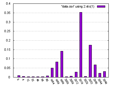
Normalized histogram, 1,000,000 measurements, discarding all bins smaller than 0.001
ADC Histogram 2
Normalized histogram, 1,000,000 measurements, using an LTC2365 in exactly the same configuration. The communications protocol is slightly different, however.
ADC Improved Histogram ADC Improved Setup
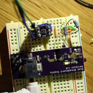
Shortening the leads to the LTC2365, moving the FPGA ground connection and braiding the FPGA wires drastically improved performance. Clearly this chip is too sensitive to interference to use on a breadboard.

ChromeOS OpenVPN to RouterOS, Part 2

Summary: to connect to RouterOS from a Chromebook, use the ONC file below but leaving out the “CompLZO” parameter completely.

Problem solved, thanks to some help from the Chromium guys. It seems that if the OpenVPN comp-lzo option is set, an extra byte is added to the packet even if this option is set to no. RouterOS documentation states that LZO is not supported, but this means that the option must be left out completely because otherwise the IP header will be received shifted by one byte. I haven’t been able to find a breakdown of what exactly the comp-lzo option changes in the OpenVPN packet, however.

A quick search showed that others have also run into this behavior, for instance this DD-WRT thread. Another thread on the OpenVPN forums suggests they are aware of the issue, but that it’s related to the configuration and pushing of options and won’t be solved before version 3.

ChromeOS OpenVPN to RouterOS

I’ve been trying to connect my Chromebook to a Mikrotik box via VPN, and thougth I’d share some of my debugging results. This is not meant to be an OpenVPN tutorial - there are plenty of those around - but will merely give what is needed to make this particular setup work.

The main issue is that it seems that remote-cert-tls has been enabeled on ChromeOS, which means that the server key must have the proper Key Usage and Extended Key Usage extensions. Using the RouterOS sign-certificate-request command will not set these, so a separate setup is required. A certificate request can be created anywhere, including on RouterOS, but to sign the key using OpenSSL you need to issue a command along the lines of:

openssl x509 -req -days 365 -in server.csr -CA ca.crt -CAkey ca.key -set_serial 01 -extensions v3_req -extfile ext.cnf -out server.crt

Note the -extensions and the -extfile arguments (thanks to emeka). The first tells x509 to go looking in the v3_req section of ext.cnf, which is a standard OpenSSL configuration file. Based on various online comments (here, for instance), make sure your ext.cnf file contains at least the following:

[ v3_req ]

keyUsage = critical, digitalSignature, keyAgreement
extendedKeyUsage = critical, serverAuth

The specification for these two lines can be found here. The two critical arguments may not be necessary, but I haven’t tested that.

The second issue is that ChromeOS by default uses UDP for OpenVPN connections, while RouterOS only supports TCP. This can be circumvented by creating an ONC file to add the VPN connection rather than using the GUI under settings. I’ve had some luck with the following (anonymized) file, the source of which I’ve forgotten:

{
    "Type": "UnencryptedConfiguration",
    "NetworkConfigurations": [
        {
            "GUID": "{vpn4us201304041651}",
            "Name": "HermesTest",
            "Type": "VPN",
            "VPN": {
                    "Type": "OpenVPN",
                    "Host": "",
                    "OpenVPN":
                            {
                            "ClientCertType": "None",
                            "CompLZO": "false",
                            "Port": 1194,
                            "Proto": "tcp",
                            "SaveCredentials": true,
                            "ServerPollTimeout": 360,
                            "ServerCARef": "{CA}"
                            }
                    }
        }
    ],
    "Certificates": [
        {
            "GUID": "{CA}",
            "Type": "Authority",
            "X509": "-----BEGIN CERTIFICATE-----...-----END CERTIFICATE-----"
        }
    ]
}

See the Open Network Configuration Format document for a reference. The X509 certificate should be the PEM certificate all on one line. Import this file via chrome://net-internals/#chromeos, and you should have a new VPN connection configured.

Don’t forget to add and your CA certificate under Settings/Certificates, and configure RouterOS as described here. This gets me as far as creating a successful connection, with both sides assigned an IP, but neither side able to ping the other. I have yet to figure out where the traffic is disappearing to.
New Soldering Station

Just acquired a Metcal soldering station, and the thing’s a real luxury compared to what I’m used to. It soldered a connector to a Star MCPCB and then some 1206 SMD capacitors to another PCB without a hitch.

For people unfamiliar with these (as I was until recently) they’re soldering irons that use RF @ 13.56 MHz to directly heat the tip of the iron. It’s a fixed-temperature system, with a heater welded to the tip so power transfer is excellent. Apparently it can’t go out of calibration, and thanks to the good power transfer you’d only really need temperature control if you were soldering thermally sensitive components. The major downside is that the tips, or “cartridges”, are noticeably more expensive than other tips.

A new MX station is very expensive, but you can get a second-hand setup for a fairly reasonable price. The old RFG-30 supplies used in the STSS stations are on eBay for $50–100, and they’re compatible with the modern MX hand-pieces and cartridges. I got a supply from an STSS-002 and a new MX-H1-AV kit (hand-piece and holder) and can confirm that they work together. The supply hums a bit, but apparently that’s normal, and in fact you can tell how much power the tip’s drawing by the intensity of the hum.

All in all, a nice piece of hardware.


Jan-willem De Bleser Jan-willem De Bleser


Rendered using cmark-gfm; styled with markdown.css, google-code-prettify and MathJax.